The Elastica software presents contact mechanical solutions with respect to purely elastic contact or deformation in an easy to use, user friendly and very fast form (no Finite Element Method). It is mainly developed for the analysis of surface contact but offers also a module for resonance frequencies of a cantilever oscillation and others.
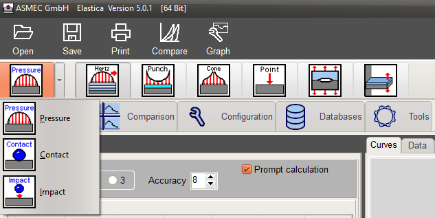
It offers solutions for spherical, flat punch and conical indenters and point forces at which only spherical indenters are of practical use.
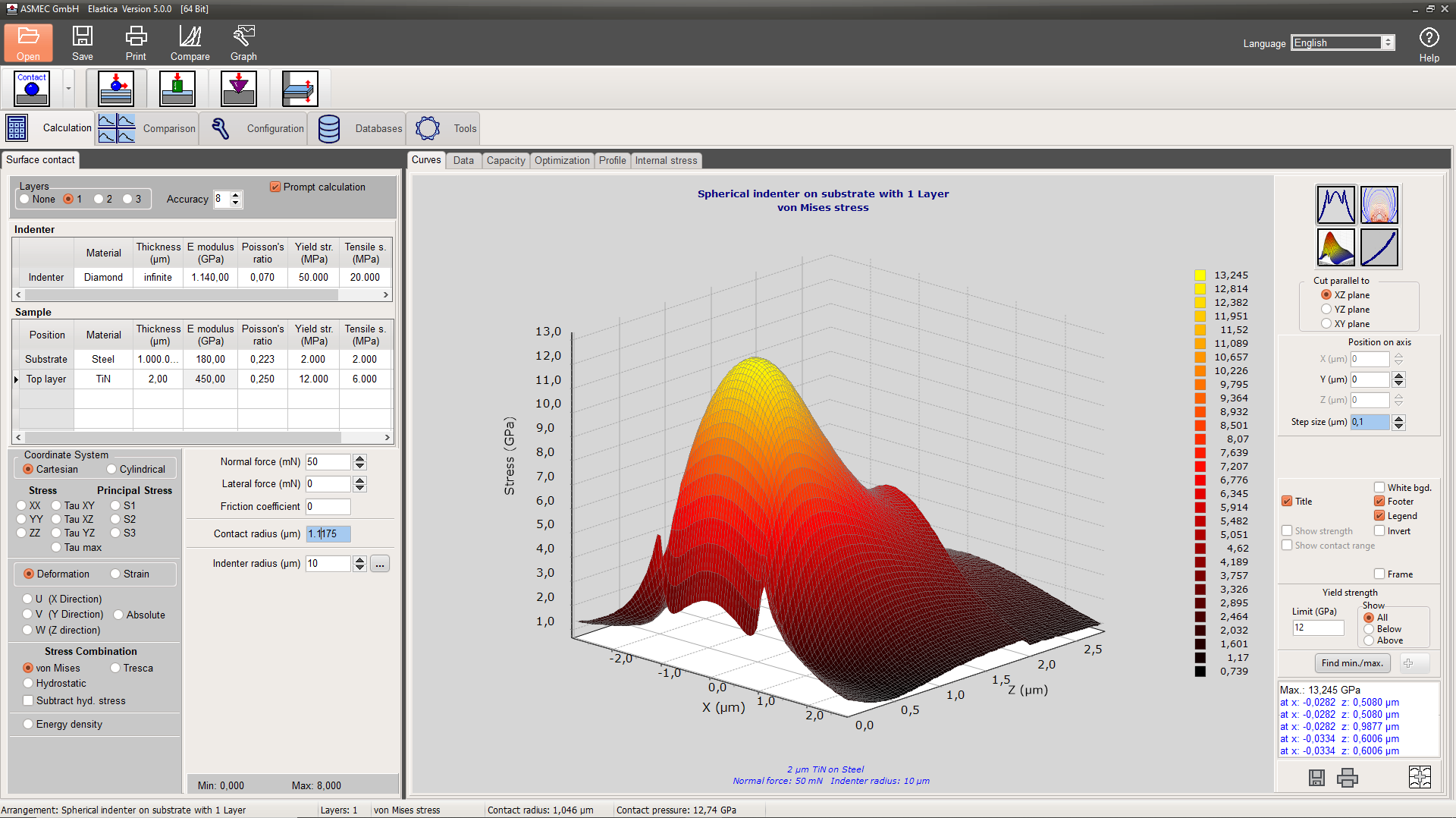
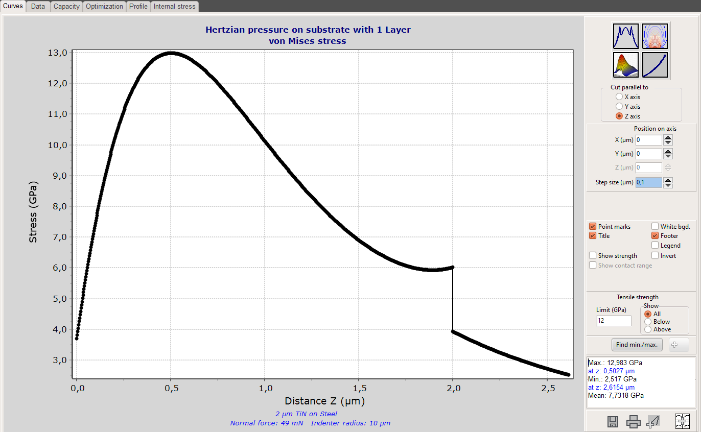
Investigation of elastic stresses, strains or deformation fields in coated surfaces during the action of static or impact forces (normal and lateral).
Fast investigation of the load carrying capacity of coated surfaces.
Optimization of coatings for mechanical protection and support of the coating design.
Analysis of indentation, scratch or wear tests and support for the design of such experiments.
Analysis of the influence of a surface profile (roughness) on the local stresses and deformations
Advantages of the ELASTICA software compared with Finite Element or Boundary Element calculations
The calculation is more than 1000 times faster due to the use of complete analytical solutions. This enables a real multi-parameter search and optimization.
Sharp stress peaks and the position and dimension of the contact area are well resolved.
Up to three layers on a substrate with thicknesses between some nanometer and several meters can be considered without redesign of the contact geometry.
Calculations of non-rotational symmetric problems, caused by tangential forces in one direction, can be done with the same calculation speed.
Main assumptions of the model
Ideally flat surface and interfaces
Homogenous and isotropic materials
Ideal adhesion of the coatings
In most cases deviations from these assumptions are not as restrictive as first suspected. Despite the idealizations, the model is delivering usable results. At least the calculations can be used to limit the search frame for a parameter optimization.
Use of the Subpages
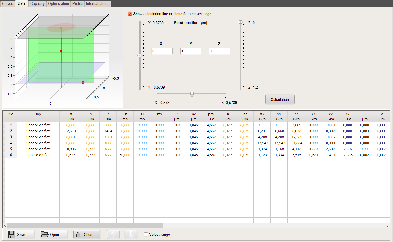
On the data page results for different positions can be calculated and collected in a table. The upper left chart is depicting the calculation range, that is defined in the configuration. Further, the red circular plane around the (0,0,0) coordinate is giving the size of the contact area.
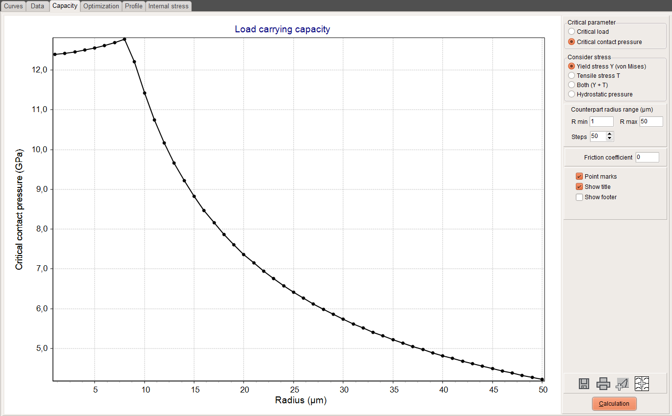
The page allows a quick calculation of the load carrying capacity of coated and uncoated materials in dependence on elastic properties, yield strength, tensile strength and radius of the counterpart. It works only for spherical indenters. The load required to produce a von Mises stress and/or a tensile stress which is equal to the yield strength or the tensile strength of the material is defined as critical load.
For coatings, the load carrying capacity depends a lot on the radius of the counterpart. The protective effect of a coating is only valid up to a certain maximum radius.
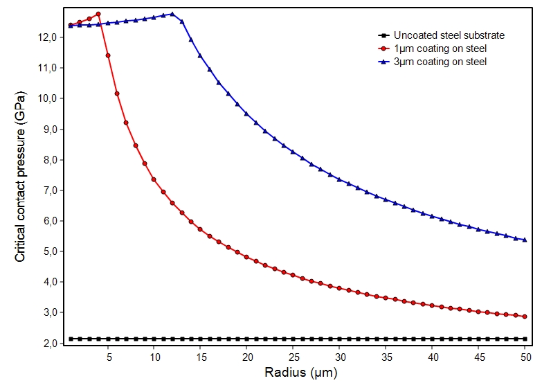
The graph is demonstrating the effect of a hard coating on the load carrying capacity and the influence of the film thickness. The increase of the thickness from 1µm to 3µm has a drastic influence on the protection effect of the coating.
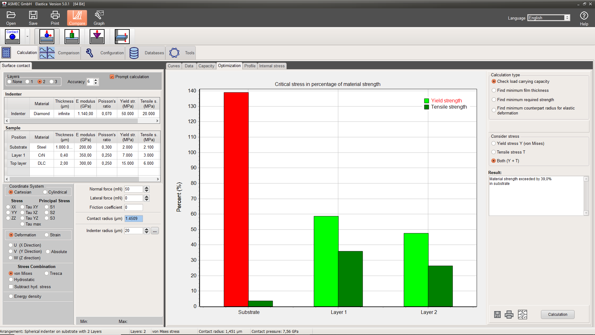
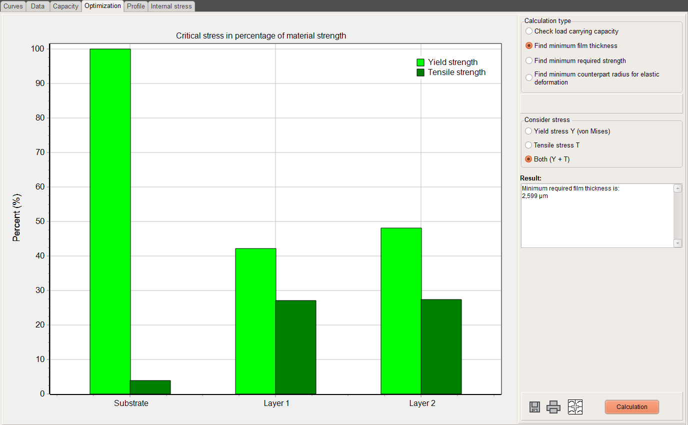
Th page gives a quick graphical overview, if the strength limits of the materials in a layered system are high enough to resist certain loading conditions. In the graph this is demonstrated for a double layer system and a 20µm radius indenter at a force of 50mN. It is shown that for a 2µm thick top layer the steel substrate is not hard enough to withstand the loading. The failure mechanism will be plastic deformation and not fracture.
The red and the light green bars show how close (in percent) the maximum von Mises stress is to the yield strength while the dark green bars show the same for the tensile strength. When the stress results are higher than 100% of the materials strengths the bars become red.
If one of the bars is red one can try to find the minimum film thickness to protect the substrate so that the strength of the substrate is not exceeded by any stress. In the given example the result is a minimum film thickness of 2.608 µm.
Alternatively, also the minimum required strengths of all materials in the stack or the minimum counterpart radius for elastic deformation can be calculated.
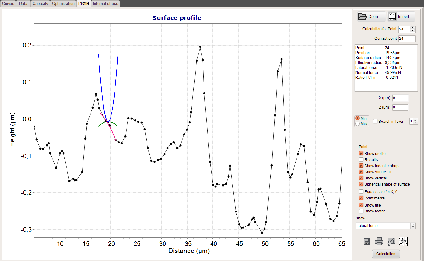
The profile page allows to read a file with a surface profile and to calculate stresses, strains or deformations along the surface in dependence on the local position and the mechanical material properties for up to 3 coatings on a substrate.
The local radius of the surface section is calculated and an effective radius is derived. The surface slope determines the force components in normal and lateral direction and both components together with the effective radius are used to derive the local stress and strain fields. For sharper roughness peaks and bigger sphere radius the contact point can deviate from the calculation point. This is considered in the calculation. The profile page shows all contact details and the stress or strain results.
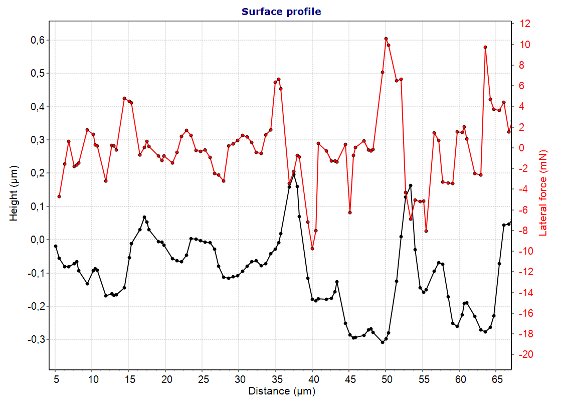
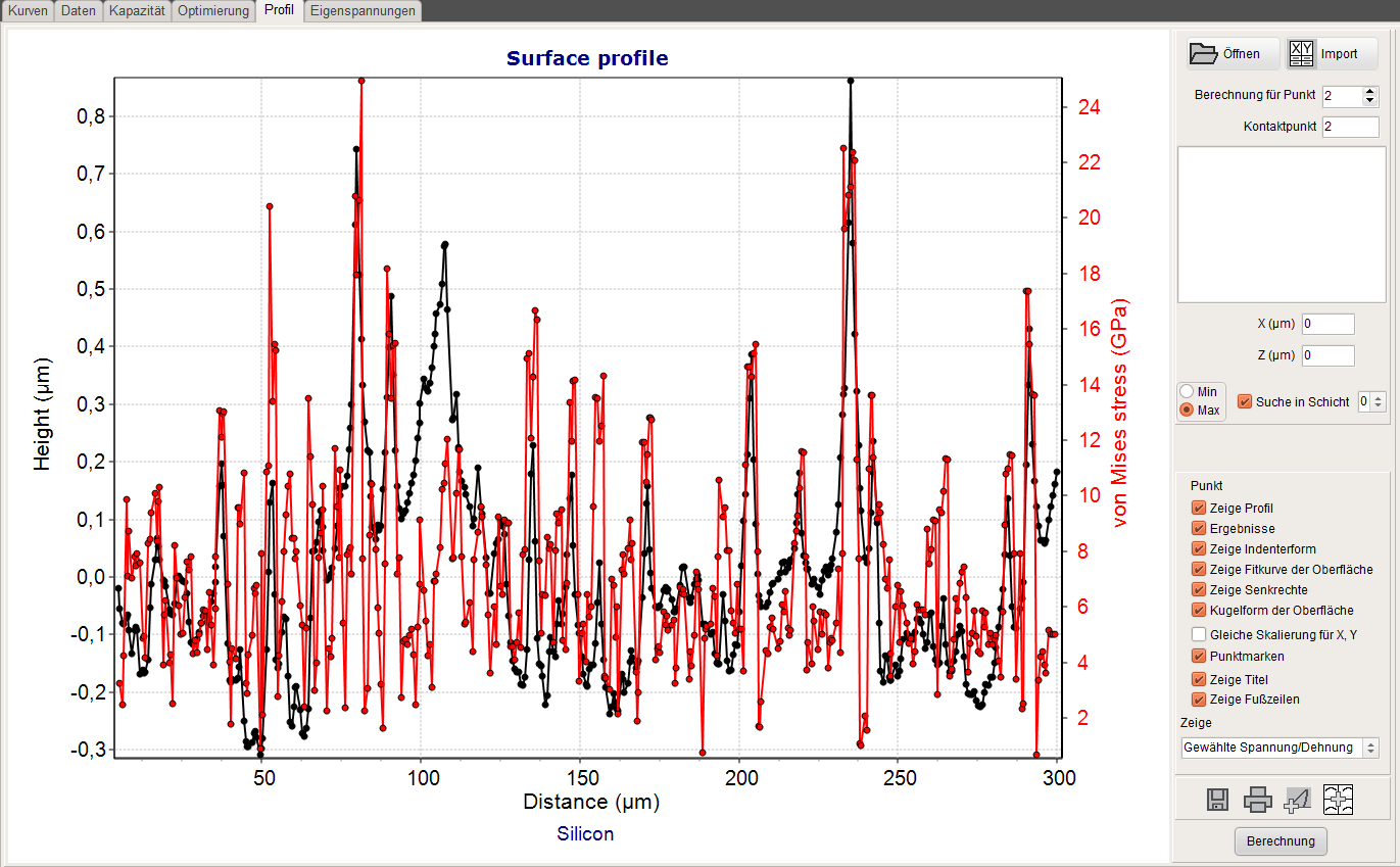
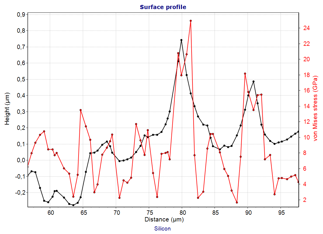
After pressing the Calculation button, the maximum of the minimum stress or strain in the selected layer or the substrate is shown for every point of the profile. Stress peaks can than easily be identified. This is demonstrated in the charts below for the von Mises stress together with the height profile. The calculation was done for an indenter of 10µm radius on a silicon sample and a force of 10mN.
The graph is showing the surface profile together with the tip shape of the spherical tip, the fit of the curvature of the surface section and the local surface radius in the contact point. The dashed line is the normal to the surface. The different scale for both axes is distorting the normal slope and the tip shape.
Due to the surface slope, the absolute force is split in a normal und lateral component, which is shown in the graph. For a positive slope the lateral force is positive and otherwise negative.
Maximum von Mises stress in the surface of an uncoated silicon sample in dependence on position along a roughness profile.
Section from the previous graph
Download
After installation this software is only working as trial version with limited rights. You have the option to test the software as full version for a period of 30 days. You only need to click on our email address in the Welcome window and to add the missing data in the prepared email. After purchasing the software you will get an access code for an unlimited period.